STROLAR® GROUND SCREWS

Ground Screw Guide

A practical guide to ground screws: site assessment, selection, installation and verification.

HomeGround Screw Guide
/ GROUND SCREW KNOWLEDGE HUB

Everything you need to know about ground screw foundations.

From how a ground screw works to where it can be used, this guide turns foundation technology into practical information for homeowners, EPCs, developers, engineers, contractors and project teams.

HOW IT WORKS

Drive. Verify. Build.

A ground screw transfers structural forces into the surrounding ground through its shaft and helical elements. The exact screw configuration and installation criteria should be selected for the project.

01PositionMark the designed foundation point.
02DriveInstall using suitable equipment.
03VerifyCheck torque, alignment and project criteria.
04BuildConnect the structure to the foundation.
Ground Screws for Solar
GROUND SCREWS FOR SOLAR

Solar foundations without the traditional concrete workflow.

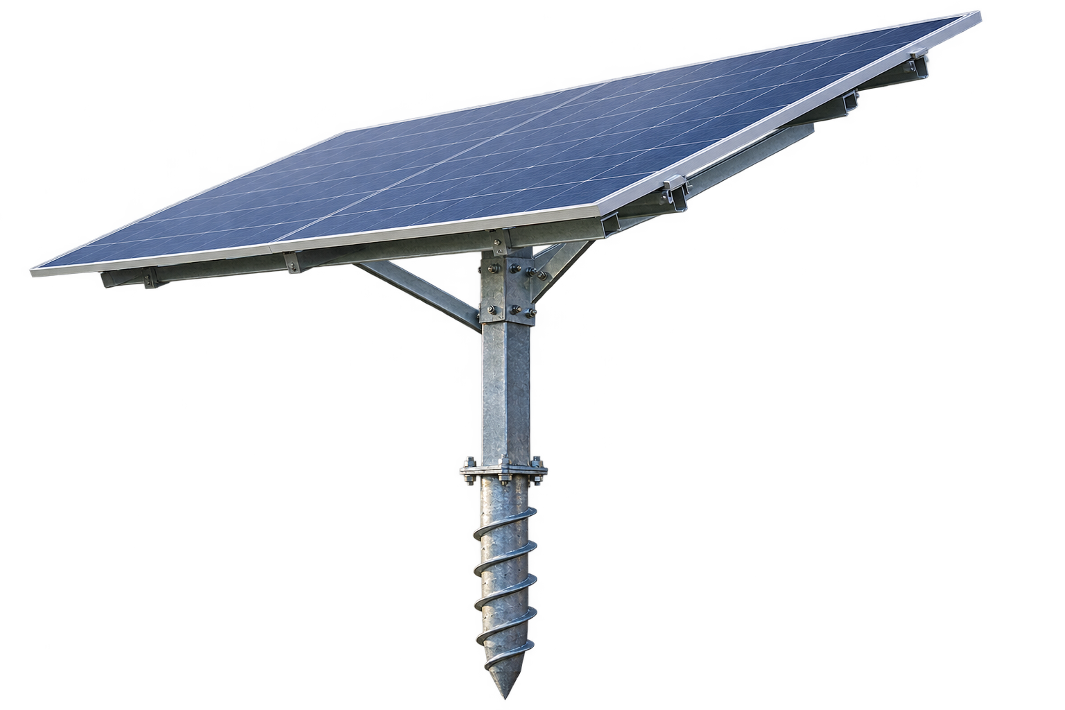
Ground screws can provide foundation points for suitable ground-mounted solar structures. A project assessment typically considers the site, soil, solar layout, structural loads, screw position, installation method and verification requirements.

Fast installationLess excavationReduced concrete dependencyImmediate foundation availability*Project-specific selectionPotential removability
*Subject to system design, installation and project requirements.
SiteMarkInstallVerifyMount
Ground Screws for Solar
GROUND SCREWS FOR FENCING

A practical foundation option for permanent and temporary fencing.

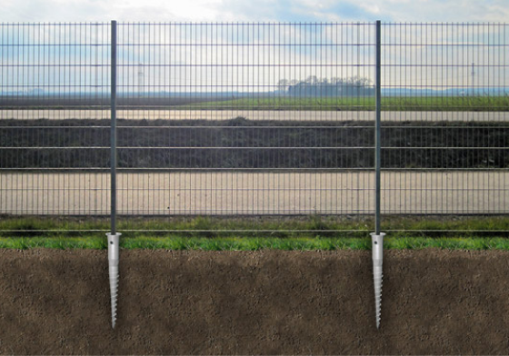
Ground screws can be paired with suitable fencing systems for industrial perimeters, construction sites, mesh or chain-link enclosures, garden boundaries, safety fences and gates. Their smaller installation footprint can be useful where excavation needs to be limited.

Fast installationSuitable for sloped sites*Easy post replacementLess excavationTemporary fencingReduced concrete dependency
*Suitability depends on terrain, loads, soil and the selected foundation system.
Ground Screws for Solar
TEMPORARY STRUCTURES

Build quickly when the foundation also needs to move with the project.

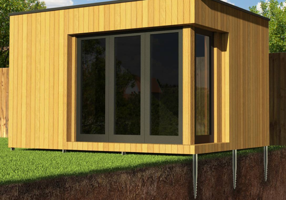
For suitable temporary applications such as event structures, cabins, walkways and lightweight structures, ground screws can reduce installation steps and may allow removal and reuse. Final capacity and stability must be established for the actual structure and site.

Quick installationNo concrete curingPotential reuseFlexible positioningReduced labourVaried terrain*
*Not every soil or structure is suitable; engineering assessment remains essential.
Ground Screws for Solar
DOMESTIC INSTALLATION

Ground screw foundations for homes, gardens and light structures.

Domestic applications can include suitable decks, garden structures, fencing, small outdoor structures and other light construction uses. Professional installation can include site assessment and quality checks appropriate to the application.

Minimal ground disturbanceQuick installationClean constructionEasy accessSuitable for selected light structuresProject-led assessment
Domestic suitability depends on structure, loads, soil and local requirements.
THE BASICS
01

What is a ground screw?

A steel foundation element with a helical section that is installed into the ground to create an anchoring point for a suitable structure.

02

How does it work?

The installed shaft and helical elements interact with the surrounding ground to transfer structural forces. Design depends on soil and loading.

03

How is it selected?

Application, soil conditions, structural loads, corrosion environment, geometry and installation requirements all influence selection.

Pull-outChecks resistance to uplift forces.
LateralChecks resistance to horizontal forces.
CompressionChecks response to downward loading.
Torque & AlignmentInstallation verification for the selected system.
/ INSTALLATION PROCESS

From site assessment to mounting.

A clear process helps align the foundation solution with the actual project.

01

Site Assessment

Understand location, ground and project constraints.

02

Soil / Project Evaluation

Review relevant ground and structural inputs.

03

Engineering & Selection

Develop a suitable foundation approach.

04

Ground Screw Installation

Install and verify position as required.

05

Mounting Structure

Connect the mounting system to the foundation.

06

Solar Installation

Proceed with module installation and project completion.

09 / TESTING, SOIL & QUALITY ASSURANCE

Installation is only one part of the foundation.

Ground screw performance depends on the interaction between the product, installation and ground. Quality assurance should therefore continue from design through execution.

Pull-Out TestEvaluates resistance to uplift forces.
Lateral TestMeasures response to horizontal loading.
Compression TestAssesses response to downward load.
Torque VerificationChecks installation resistance against project criteria.
Position & AlignmentConfirms installed foundation location and orientation.
GPS / Site RecordsDigital location records can support installation traceability.
01

Soil

Profile, density, fill, clay, sand, rock and moisture conditions can affect selection.

02

Terrain

Slope, access, drainage and site logistics can influence installation.

03

Environment

Corrosion exposure, weather and project life influence material and protection choices.

04

Structure

Wind, seismic, compression, uplift, lateral loads and connection geometry matter.

BENEFITS & ADVANTAGES

Why the ground screw foundation workflow can be valuable.

A ground screw is more than a steel component. Project benefits come from the interaction between foundation geometry, installation method, ground conditions and the supported structure.

BENEFITS / ADVANTAGES

Why choose a ground screw foundation?

The strongest case for ground screws is not one feature — it is the combination of installation method, site impact, verification and project speed.

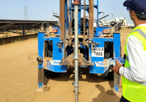
Ground screw installation machine working beside solar mounting frames Installation reference visual
01

Easy Installation

Mechanical installation can reduce the conventional excavation, formwork and curing sequence on suitable projects.

02

Project Speed

Once installed and verified, the foundation point can be prepared for the next construction stage without waiting for concrete to cure.

03

Consistent Quality

Installation records, torque verification and position checks can create a controlled foundation workflow.

04

Potential Reuse

Some systems can be removed and reused in suitable temporary applications, reducing permanent site intervention.

05

Lower Site Disturbance

Less conventional excavation can mean less spoil, less wet work and a smaller installation footprint.

06

All-Season Potential

Mechanical installation can be less dependent on concrete curing conditions, subject to site access and ground conditions.

07

Terrain Adaptability

Foundation points can be designed for varied terrain and levels, reducing the need for extensive site levelling in suitable applications.

08

Engineered Performance

Pull-out, lateral and compression testing can be used where project requirements call for field verification.

HOW THE BENEFITS COME TOGETHER

Why the installation method matters.

A ground screw is more than a steel component. The project benefit comes from the interaction between the foundation geometry, installation method, ground conditions and the structure being supported.

01

Understand the site

Review location, terrain, access and available ground information before foundation selection.

02

Match the system

Select geometry and connection details around the supported structure and project loads.

03

Install mechanically

Use suitable installation equipment and controlled procedures for the selected system.

04

Verify where required

Use installation records and project-specific testing when engineering requirements call for it.

GROUND SCREWS VS. TRADITIONAL CONCRETE

Different foundation workflows.

Ground screws do not replace every foundation solution. The useful comparison is the construction workflow and the conditions under which each approach is suitable.

GROUND SCREW WORKFLOW
Site preparationPositioning and access planning.
Mechanical installationInstall the selected foundation element.
VerificationRecords and tests where required.
Structure connectionConnect the supported frame.
VS
CONVENTIONAL CONCRETE WORKFLOW
Excavation / preparationExcavate and prepare the foundation area.
Formwork / reinforcementPrepare the concrete foundation system.
Concrete placement & curingConcrete-related construction sequence.
Structure connectionProceed after the required foundation stage.
The appropriate foundation method depends on structural design, geotechnical conditions, local requirements, installation access and project economics.
WHERE BENEFITS CAN MATTER

Applications where the foundation workflow can be valuable.

Different projects value different advantages. Solar may prioritise installation speed and repeatability; temporary structures may value removability; sensitive sites may value reduced conventional excavation.

Solar

Repeated foundation points across large mounting layouts.

Agri-PV

Potentially useful where agricultural use and foundation planning must coexist.

Fencing

Point foundations for selected perimeter and gate systems.

Temporary Structures

Useful where the project may require a removable foundation approach.

Domestic

Garden rooms, decks and selected lightweight structures.

Light Structures

Selected modular, prefab and light steel applications.

IMPORTANT PROJECT CONSIDERATIONS

Benefits only matter when the system is correctly selected.

Ground conditions

Soil profile, density, obstructions, groundwater and terrain can affect foundation selection and installation.

Design loads

Wind, uplift, lateral and compression actions must be considered by the responsible engineer.

Geometry & connection

Head, shaft and helical configuration should suit the supported structure and required connection.

Installation access

Equipment access, working space and site logistics influence practical installation planning.

Verification

Testing and installation records can provide project-specific evidence where required.

Engineering responsibility

Final foundation design and suitability should be established by the responsible structural/geotechnical team.

QUICK ANSWERS

What should you know before choosing ground screws?

Are ground screws suitable for every soil?

No. Suitability depends on the soil profile, installation conditions, structural loads and the selected screw system. Site investigation and engineering assessment may be required.

Do ground screws always eliminate concrete?

They can provide a concrete-free foundation approach for suitable applications, but the complete project may still use concrete elsewhere depending on the structure and design.

Can they be used for solar projects?

Yes, ground screws are commonly considered for ground-mounted solar foundations, subject to project-specific structural and geotechnical requirements.

Can ground screws be removed?

Some systems can be removed in suitable temporary applications. Reuse depends on condition, design and project requirements.

QUALITY TESTING & VERIFICATION

Testing ground screw behaviour under project-specific conditions.

Testing should be planned around the project loads, ground conditions and acceptance criteria established by the responsible engineering team.

GROUND SCREW QUALITY TESTING

Test the foundation. Know the ground.

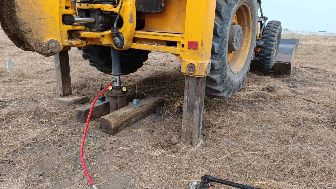
Quality testing verifies how an installed foundation responds to the loads relevant to the project. The reference testing workflow covers pull-out, lateral and compression tests.

FIELD VERIFICATION
Ground screw pull-out test rig
01 / UPLIFT

Pull-Out Test

Evaluates resistance to vertical uplift forces. This is relevant to wind uplift and other tension-dominated load cases.

  • Load resistance
  • Foundation stability
  • Site-specific verification
Ground screw lateral testing setup
02 / STABILITY

Lateral Test

Measures response to horizontal forces such as wind, seismic actions or soil movement where lateral capacity is important.

  • Horizontal load capacity
  • Deflection behaviour
  • Wind / seismic design support
Ground screw compression test setup
03 / LOAD-BEARING

Compression Test

Assesses downward load-bearing behaviour and helps verify performance for high-load structures.

  • Compression capacity
  • Settlement response
  • Heavy-structure support

Test configuration, acceptance criteria and required test loads are project-specific and should be defined by the responsible structural/geotechnical engineer.

FIELD VERIFICATION WORKFLOW

From installation to measurable foundation behaviour.

Testing should be planned around the project loads, ground conditions and the acceptance criteria established by the responsible engineering team.

01

Select test location

Identify representative foundation points and site conditions.

02

Install test foundation

Install the selected ground screw using the planned procedure.

03

Apply test load

Measure response under the defined uplift, lateral or compression load.

04

Record & assess

Compare measured behaviour against project-specific requirements.

GROUND SCREW SELECTION

Select the foundation around the project — not the other way around.

01

Application

Understand what structure the foundation will support.

02

Ground Conditions

Review soil, terrain, obstructions and available ground information.

03

Structural Loads

Consider uplift, lateral and compression actions.

04

Geometry & Connection

Match shaft, helix and head configuration to the structure.

05

Installation

Confirm equipment access and installation procedure.

06

Verification

Use records and testing where project requirements call for it.

GROUND SCREW FAQ

Common technical questions.

What is a ground screw?

A ground screw is a steel foundation element installed into the ground mechanically, typically using a shaft and helical plates to engage the surrounding soil.

Can ground screws replace concrete?

They can provide a concrete-free foundation approach for suitable applications, but final suitability depends on structural and geotechnical requirements.

Are ground screws suitable for every soil?

No. Soil profile, density, obstructions, groundwater, installation access and required capacity all influence suitability.

How are ground screws tested?

Project-specific testing can include pull-out, lateral and compression tests, along with installation records and other verification methods.

Can ground screws be removed?

Some systems can be removed for suitable temporary applications. Reuse depends on the condition of the product, design and project requirements.

Do ground screws require engineering?

Foundation selection and final design should be established by the responsible structural/geotechnical engineering team for the specific project.